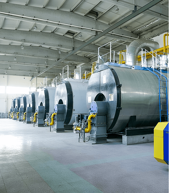
In industrial boiler operation, slagging and ash deposition are common problems in heat exchange systems. Slagging is the process by which ash from fuel combustion melts at high temperatures and adheres to the boiler's heating surfaces and furnace walls, forming hard deposits; ash deposition, on the other hand, involves the accumulation of unmelted fine ash particles, which can be removed by conventional soot blowing.
Severe slagging significantly affects boiler safety and operating efficiency. Slag layers reduce the heat transfer coefficient of the heating surfaces, leading to increased flue gas temperature at the furnace outlet and increasing the risk of overheating and damage to superheaters and reheaters. Slag detachment can also cause accidents such as water wall tube ruptures and flue gas blockage. At the same time, slagging reduces boiler thermal efficiency by 3%-8%, increasing fuel consumption and significantly raising operating costs.
The core characteristic of boiler slagging is that the ash undergoes a complete process of melting, adhesion, and solidification, forming a hard, strongly adhesive slag that cannot be removed by simple soot blowing. Ash deposition, however, does not involve ash melting; the deposited ash particles are loose and can be effectively cleaned using soot blowing devices. There are fundamental differences between the two in terms of formation mechanism and treatment difficulty.
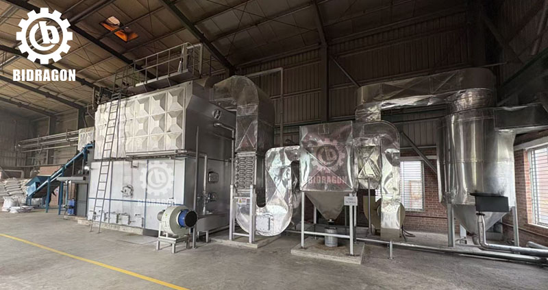
In industrial boilers, slagging mostly occurs in areas such as the furnace water walls, around the burners, and on the heating surfaces of superheaters and reheaters. These areas are constantly exposed to high temperatures and are in direct contact with flames or high-temperature flue gas, making them high-risk areas for ash melting and adhesion. The furnace water walls, due to their direct exposure to the combustion flame, have the highest probability of slagging, accounting for over 60% of industrial boiler slagging cases.
Industrial boilers are more prone to slagging than other types of boilers, such as power plant boilers. The main reason is the wide adaptability of fuels and the large fluctuations in their composition. Most industrial boilers need to be compatible with various fuels such as coal, biomass, and waste oil, making it difficult to stably control the ash content and composition of the fuel. At the same time, industrial boilers experience frequent load fluctuations and unstable operating conditions, leading to localized overheating in the furnace. Furthermore, the arrangement of heating surfaces is limited by equipment size, resulting in poor flue gas flow and easy deposition and melting of ash.
The melting point of fuel ash is a key indicator in determining whether fouling will occur. Ash melting point is usually characterized by deformation temperature, softening temperature, and flow temperature. When the local temperature in the furnace exceeds the ash softening temperature, the surface of the ash particles begins to melt, increasing viscosity, and quickly adhering to the heated surface to form a slag layer. In industrial boilers, the softening temperature of lignite ash is generally between 1100℃ and 1250℃, far lower than that of bituminous coal (1300℃ to 1500℃). Therefore, the risk of fouling is significantly higher when using lignite as fuel compared to bituminous coal.
The alkali metal content in coal and biomass fuels significantly affects fouling. Alkali metals such as sodium and potassium form low-melting-point compounds during combustion, with melting points as low as 800℃ to 900℃. These compounds coat the surface of ash particles, lowering the overall ash melting point and accelerating the fouling process. In biomass fuels such as wood chips and straw, the sodium content is usually between 0.5% and 2.0%, which is 5 to 10 times higher than that of bituminous coal. This is the core reason why fouling is a prominent problem in biomass boilers.
There are significant differences in the fouling characteristics of pulverized coal boilers and biomass boilers. Fouling in pulverized coal boilers is mostly concentrated in the upper part of the furnace and the burner nozzle area. The slag is mostly hard, grayish-black lumps, with unburned pulverized coal particles interspersed within. This is because the combustion speed of pulverized coal is fast, and the local temperature can easily soar to above 1600℃, far exceeding the ash softening temperature. Fouling in biomass boilers, however, exhibits a more widespread characteristic, with slag layers potentially appearing from the furnace to the tail flue. The slag is mostly loose and porous, easily detached but regenerates quickly. This is mainly due to the condensation of alkali metal vapors produced by biomass combustion on low-temperature heated surfaces, leading to both low-temperature and high-temperature fouling problems. In a European biomass power generation project, an industrial boiler using straw as fuel experienced severe superheater fouling after only 200 hours of operation due to uncontrolled alkali metal content, forcing a shutdown for cleaning and resulting in direct economic losses exceeding 150,000 euros.
Local overheating in the furnace is a direct cause of slagging. The design temperature of industrial boiler furnaces is typically between 1300°C and 1500°C. However, when combustion is improperly adjusted or there are sudden load changes, local temperatures may exceed 1600°C, at which point even high-melting-point ash will melt. For every 100°C increase in furnace temperature, the ash viscosity increases by 30% to 50%, significantly increasing the probability of adhesion to the heating surfaces.
A reducing atmosphere in the furnace significantly lowers the ash melting point. In a reducing atmosphere, increased carbon monoxide concentration reduces ferric oxide in the ash to ferrous oxide. Ferrous oxide then forms low-melting-point eutectic compounds with silicon dioxide and aluminum oxide, lowering the ash softening temperature by 100°C to 200°C. When the oxygen content in the furnace is below 3%, a reducing atmosphere predominates, increasing the risk of slagging by 2 to 3 times.
Pulverized coal furnaces have a unique temperature-dependent slagging mechanism. The combustion process of pulverized coal in the furnace is divided into three stages: preheating, combustion, and burnout. If the primary and secondary air ratios are improper, the pulverized coal may not be fully mixed during the preheating stage, leading to localized high coal concentration and the formation of a localized high-temperature flame core. The temperature in the flame core can reach 1700°C to 1800°C, causing the ash to melt instantly and adhere to the surrounding water-cooled walls, forming high-temperature slagging.
Uneven air distribution and burner deviations are the main operational factors leading to slagging. If industrial boiler burners experience problems such as nozzle blockage or angle deviation, it will cause turbulent airflow in the furnace, resulting in uneven mixing of oxygen and fuel, creating localized fuel-rich and oxygen-deficient areas. In the fuel-rich areas, combustion is incomplete, leading to concentrated heat release and increased temperature; in the oxygen-deficient areas, a reducing atmosphere is formed, and the combined effect accelerates slagging. Slagging caused by air distribution deviations accounts for more than 70% of operational slagging cases.
Frequent load fluctuations can lead to temperature fluctuations, exacerbating the risk of slagging. When the load of an industrial boiler increases from 50% to 100% of its rated load, the furnace temperature rises from approximately 1200℃ to 1500℃. If the load fluctuation frequency exceeds twice per hour, the temperature frequently crosses the ash softening temperature range, causing ash particles to repeatedly adhere in molten and semi-molten states, increasing the slagging rate by 1.5 times. Load fluctuations also lead to changes in flue gas velocity, increasing ash deposition efficiency and further promoting slag formation.
During boiler startup and shutdown, and during oil firing, the risk of slagging is significantly higher than during normal operation. During startup and shutdown, the furnace temperature rises slowly, resulting in incomplete fuel combustion, and ash is easily deposited on the heating surfaces; during oil-assisted combustion, although the ash content of the fuel oil is low, the combustion temperature is high, and oil mist easily adheres to ash particles, forming an oily slag layer.
A chemical processing facility’s boiler suffered from accelerated slagging after transitioning to a "load-following" mode to support variable steam demand. The frequent ramping between 50% and 100% load caused the flame center to shift vertically, causing "thermal shock" on the superheater tubes. This cyclic heating and cooling allowed semi-molten ash to bond more tightly to the metal surfaces. Within a month, the flue gas resistance increased by 25%, and the plant reported a significant drop in thermal efficiency due to the insulating effect of the newly formed slag layers.
The arrangement of heating surfaces significantly affects ash deposition. If the spacing between heating surfaces in an industrial boiler is too small or the arrangement is irregular, it will increase flue gas flow resistance, reduce flow velocity, and prolong the residence time of ash particles on the heating surface, increasing the probability of deposition. If the spacing between heating surface tube rows is less than 3 times the tube diameter, eddy current zones are easily formed when the flue gas flows around the tubes, and ash deposits in these eddy current zones and gradually melts.
Excessively high metal wall temperatures directly lead to ash adhesion. If the metal wall temperature of the heating surface in an industrial boiler exceeds the ash softening temperature, ash particles will quickly melt and adhere upon contact with the wall, forming a slag layer. The metal wall temperature at the superheater outlet is usually designed to be 540℃ to 560℃. If poor heat transfer causes the wall temperature to rise above 600℃, even if the flue gas temperature does not exceed the ash melting point, slagging will still occur due to the high wall temperature.
Industrial water-tube boilers have unique structural slagging problems. In water-tube boilers, the heating surfaces are arranged in the form of tube bundles. When the flue gas flows transversely across the tube bundles in the furnace, the flow velocity distribution is uneven, and low-velocity zones are easily formed on the leeward side of the tube bundles, resulting in severe ash deposition. Meanwhile, water-tube boilers have relatively small furnace volumes, resulting in insufficient flame coverage and easily leading to excessively high local temperatures. The gaps between the tube bundles are also prone to blockage by slag. Once slag formation occurs, cleaning is far more difficult than with fire-tube boilers.
Fuel control and coal blending are fundamental measures for preventing slag formation. The fuel ash content must be strictly controlled, keeping the ash mass fraction below 15%, and the ash melting point should be tested to ensure the ash softening temperature is no lower than 1300℃. For multi-fuel boilers, coal blending can be used to adjust the fuel composition. Mixing high-ash-melting-point fuel with low-ash-melting-point fuel in a ratio of 7:3 to 8:2 can increase the ash melting point of the mixed fuel by 100℃ to 150℃. However, coal blending increases fuel procurement and storage costs, and requires specialized blending equipment, which may pose an investment challenge for small industrial boiler companies.
Combustion optimization to limit furnace temperature is crucial. The core principle is to control the furnace outlet flue gas temperature below 1200℃, with local temperatures not exceeding 1500℃. By adjusting the burner load distribution, the output deviation of each burner should be controlled within ±5% to avoid localized fuel concentration and combustion. Flue gas recirculation technology, which introduces low-temperature flue gas from the tail end into the furnace, can reduce the furnace temperature by 50℃ to 100℃. However, this technology slightly reduces combustion efficiency, increasing fuel consumption by 2% to 3%, requiring a trade-off between slag prevention and energy consumption.
Staged air supply and oxygen control can effectively suppress the formation of a reducing atmosphere. Using a staged secondary air supply system, the secondary air is divided into three layers (upper, middle, and lower), with a flow rate distribution ratio of 3:4:3, ensuring uniform oxygen distribution in the furnace. Controlling the oxygen content at the furnace outlet to between 3% and 5% can significantly reduce carbon monoxide concentration and prevent a decrease in the ash melting point. However, staged air supply requires modification of the air supply system, adding control valves and monitoring equipment, resulting in high initial investment and requiring frequent air volume adjustments during operation, increasing operational complexity.
Soot blowing and heating surface temperature management are key aspects of preventing slag formation. Based on the boiler operating conditions, a regular soot blowing schedule is established. The furnace water walls are blown with soot every 8 hours, and the superheaters and reheaters are blown every 4 hours. Steam or sonic soot blowing methods are used, with the blowing pressure controlled between 1.5 MPa and 2.0 MPa. Simultaneously, the metal wall temperature of the heating surfaces is monitored, and the temperature deviation is controlled within ±10℃ to prevent localized overheating. The soot blowing process consumes steam or electricity, increasing operating costs, and excessive soot blowing may lead to wear on the heating surfaces. Therefore, the frequency and pressure of soot blowing need to be controlled to balance the anti-fouling effect with equipment wear.
Coking in pulverized coal boilers is mainly high-temperature coking, concentrated in the upper part of the furnace, the burner nozzle, and the superheater area. The coking rate is fast, and the coke is hard, mainly due to the high combustion temperature of pulverized coal and concentrated flames, where local temperatures easily exceed the ash softening temperature. Coking in pulverized coal boilers is closely related to the fineness of the pulverized coal. When the fineness R90 is controlled between 15% and 20%, combustion is complete and coking is less likely. If the fineness exceeds 25%, coarse pulverized coal particles do not burn completely, easily leading to localized high-temperature coking.
The coking risk in circulating fluidized bed boilers mainly comes from bed coking, which is divided into low-temperature coking and high-temperature coking. Low-temperature coking often occurs when the bed temperature is below 850℃, and the fuel is not fully combusted, causing ash to deposit in the bed and form loose coke lumps; high-temperature coking occurs when the bed temperature exceeds 950℃, causing the bed material to melt and adhere, forming hard coke. When limestone is used for desulfurization in circulating fluidized bed boilers, adding more than 3% limestone will lower the bed melting point and increase the risk of coking. The limestone addition should be controlled between 1% and 2% to balance the desulfurization effect and the coking risk.
Biomass and waste incineration boilers have unique coking problems, primarily due to the synergistic effect of alkali metals and chlorine, which accelerates coking. Biomass and waste have high chlorine content, and during combustion, alkali metal chlorides are formed, which have low melting points (600℃ to 700℃) and easily condense on the heating surfaces, causing corrosion and coking. Coking in these boilers exhibits a multi-layered structure, with a loose ash layer on the outside and a corrosive coke layer on the inside. This makes cleaning difficult, and the coke layer exacerbates corrosion of the heating surfaces, shortening the equipment's service life. An industrial boiler in a Japanese waste incineration power plant, due to the lack of dechlorination measures, experienced severe coking and corrosion in the tail flue after only one year of operation, resulting in heating surface replacement costs exceeding US$1 million.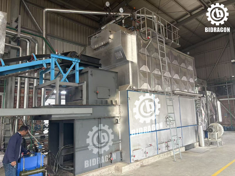
Different chemical components in the ash have different effects on the ash melting point. Silicon dioxide is the main component of ash, typically accounting for 40% to 60% of its composition. Its melting point is as high as 1723℃. Increasing the silicon dioxide content can raise the ash melting point, but excessively high levels lead to increased ash viscosity and easier deposition. Ferric oxide content ranges from 5% to 15%, and in a reducing atmosphere, it is reduced to ferrous oxide. Ferrous oxide and silicon dioxide form a low-melting point eutectic, lowering the ash melting point by 100℃ to 150℃.
Calcium oxide and sodium oxide have different effects on the ash melting point. When the calcium oxide content is between 10% and 20%, it can form high-melting point compounds with silicon dioxide and aluminum oxide, increasing the ash melting point; however, when the content exceeds 25%, it forms a low-melting point eutectic, lowering the ash melting point. Even a sodium oxide content of only 1% to 2% will significantly lower the ash melting point, as sodium oxide readily forms eutectics with other components, and their eutectic temperatures are generally below 1000℃.
The formation of low-melting point eutectics is the core chemical mechanism of slagging. When various components in the ash are mixed, binary or ternary eutectics are formed, whose melting points are far lower than those of the individual components. Common low-melting point eutectics include silicon dioxide-ferrous oxide (melting point 1170℃), silicon dioxide-calcium oxide-sodium oxide (melting point 880℃), etc. These eutectics easily melt at furnace temperatures and adhere to the heated surfaces, forming slag layers. Ash viscosity is directly related to slagging adhesion. Ash viscosity initially decreases and then increases with increasing temperature. In the temperature range from the ash softening temperature to the flow temperature, the ash viscosity is between 10^2 and 10^5 Pa·s, at which point the adhesion is strongest and the slagging rate is fastest.
The water-cooled walls of the furnace are the most prone to slagging in industrial boilers. The water-cooled walls are in direct contact with the combustion flame, and the wall surface temperature is between 400℃ and 600℃, while the flame center temperature reaches 1500℃ to 1600℃. The ash melts at high temperatures and easily adheres to the surface of the water-cooled walls. After slagging occurs on the water walls, heat transfer efficiency decreases, leading to an increase in flue gas temperature at the furnace outlet, further exacerbating slagging in other areas.
Slagging in the burner and flame impingement areas is often due to flame deviation or nozzle blockage. The burner nozzle temperature is high, and if accumulated ash is not cleaned in time, it can lead to uneven fuel injection, flame deviation, and impingement on surrounding heating surfaces, causing ash to rapidly adhere to the impingement area. Slagging in the flame impingement area further blocks the nozzle, creating a vicious cycle and affecting combustion stability.
Slagging in the superheater and reheater sections is mainly due to high flue gas temperature and low flow velocity. The superheater and reheater are located at the furnace outlet, where the flue gas temperature is between 800℃ and 1000℃. Although lower than the furnace temperature, the molten components in the ash remain viscous in this area, and the reduced flue gas velocity makes it easy for ash particles to deposit and adhere. Slagging in this area leads to poor heat transfer on the heating surfaces, resulting in excessive steam temperature, and in severe cases, causing tube rupture accidents.
Abnormal furnace temperature distribution is one of the early signs of slagging. If the furnace temperature monitoring system detects that the temperature in a local area exceeds 1600℃, and the temperature deviation exceeds 100℃, while the flue gas temperature at the furnace outlet continues to rise, exceeding the design value by more than 50℃, it indicates a trend of slagging. Abnormal temperature distribution usually appears 24 to 48 hours before visible slagging, making it a key indicator for early identification.
Changes in resistance and heat transfer performance can directly reflect the slagging situation. Boiler flue gas resistance increases with the degree of slagging. When the induced draft fan current increases by 10% to 15%, and the furnace negative pressure fluctuation exceeds ±50Pa, it indicates that there is slag buildup blocking the flue gas path. At the same time, the heat transfer performance of the heating surface decreases, manifested as a decrease in boiler evaporation, and an increase in fuel consumption under the same load. When the evaporation rate decreases by more than 5%, and fuel consumption increases by more than 3%, slagging problems need to be investigated.
Other slagging signals reflected in operating parameters include fluctuations in steam temperature and pressure. When slagging causes poor heat exchange in the superheater, the superheated steam temperature will rise, exceeding the normal temperature by more than 10℃, and temperature control becomes more difficult. Simultaneously, boiler drum pressure fluctuations increase, and the deviation between feedwater flow and steam flow widens. These parameter changes require comprehensive judgment based on temperature and resistance data to avoid misjudgment.
Daily inspection and slag removal methods should be combined with the boiler type and the degree of slagging. Regular endoscopic inspections of the furnace and superheater areas for slagging should be conducted at least once a month. When mild slagging is detected, online soot blowing can be used for cleaning; when the slag thickness exceeds 20 mm, the boiler needs to be shut down for cleaning using high-pressure water jet or mechanical slag removal methods. High-pressure water jet cleaning pressure should be controlled between 20 MPa and 30 MPa, which can effectively remove hard slag layers, but may cause slight wear on the heating surface. Mechanical slag removal is prone to leaving residual slag, resulting in limited cleaning effectiveness.
Operating procedures play a crucial role in preventing slagging. Strict operating manuals should be developed, clearly defining key parameters such as air-fuel ratio, load fluctuation range, and soot blowing frequency. Operators must receive professional training to avoid improper operation. For example, during load adjustment, the hourly load change should not exceed 10% of the rated load. During boiler start-up and shutdown, the rate of temperature and pressure increase should be strictly controlled to avoid sudden local temperature increases. Implementing operating procedures requires investment in personnel training costs and the establishment of a supervision mechanism. Small enterprises may face challenges in implementing these procedures due to insufficient manpower.
Integrating slagging control into the daily management system requires establishing a slagging monitoring and recording system, regularly analyzing the causes of slagging, and optimizing prevention strategies. A comprehensive assessment of boiler slagging should be conducted quarterly, combining data on fuel composition, operating parameters, and slag removal records to adjust coal blending ratios, soot blowing frequency, and other measures. Simultaneously, a equipment maintenance plan should be established to regularly check the performance of burners, soot blowers, and other equipment, and replace damaged parts promptly to prevent slagging caused by equipment failure. Establishing this management system will increase management costs, but it can significantly reduce the incidence of slagging accidents and extend the boiler's service life.
The formation of slagging in industrial boilers is the result of the combined effects of multiple factors, including fuel type, temperature, operating conditions, and equipment structure. The core mechanism is the melting and adhesion of ash under high temperature and reducing atmosphere conditions. Preventing slagging requires a focus on source control, employing various measures such as fuel optimization, combustion adjustment, and equipment maintenance to inhibit slag formation.